
Construction
Conductor
Litz's thread is a enamelled copper wire which may be weldable or non-weldable in Grade 1
(1 coat of enamel) or Grade 2 (2 coats of enamel)
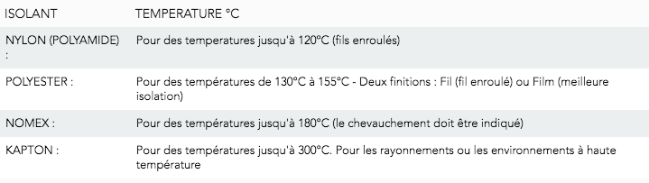
THERMAL CLASS | F155 (155°C) | H180 (180°C) | 200 (200°C) |
|---|---|---|---|
Enamel type | Polyurethane | Polyester or Polyurethane | Polyester ou polyamide |
Wiring
Conductors wired into 7 wire studs and these wired into perfect wiring formation (7, 19, 37) with matched pitch. The formation and number of threads depend on the section and the working frequency thereof. We can also manufacture in square or rectangular shape, depending on the need.
Insulation: According to different materials, according to the temperature and their use
Characteristics
Cables made of fine enamelled copper wire. Unit threads from 0.05 mm Ø to 5 mm
The choice of the diameter of a single wire is important for the specific application
The table below shows the relationship between the recommended single wire diameter and the frequency range.
Frequency Min (KHz) | Frequency Max (KHz) | Recommended wire diameter (mm) |
|---|---|---|
0,06 | 1 | 0,32 |
1 | 10 | 0,25 |
11 | 20 | 0,18 |
21 | 50 | 0,12 |
51 | 100 | 0,1 |
101 | 350 | 0,06 |
351 | 850 | 0,05 |
851 | 1400 | 0,04 |
1401 | 3000 | 0,03 |
Application
It is a special type of wire used in electronics. It is made up of several wires covered with an insulating film, twisted and connected in parallel at their ends. The use of many wires in parallel increases the surface area of the conductive surface and thus reduces the influence of the skin effect *. For them, their applications are very diverse:
Electric automobile
Medicine-health (magnetic resonance equipment)
Renewable energy
Aeronautics / airspace
Railway industry
Electrical connections
*Skin effect: A phenomenon of electromagnetic origin dictating that at high frequencies, an electric current will flow rather on the surface of a conductor than inside.
Source : https://www.allaboutcircuits.com
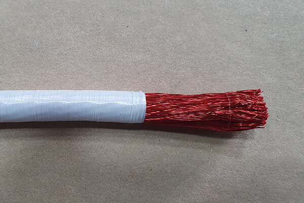 Le câble de Litz est la réunion de plusieurs fils de Litz.
Le câblage se fait en couches concentriques, pour réaliser la section nécessaire (7 x 7 x 37).
Nous pouvons aussi fabriquer sous forme carrée ou rectangulaire, selon le besoin.
Nous pouvons également mettre une couche d’isolation textile.
Le câble de Litz se définit par le nombre de fils et le diamètre unitaire des fils :
Exemple : 120 X 0,10mm = 120 brins de diamètre 0,10mm.

We produce Litz cables in different ways following the recommendations of the Design Office. TESORAX manufactures them with the wires assembled in the same direction and with a strand pitch of less than 60mm. On request, and to meet the needs of our customers, we can form them into rectangular or square sections in order to reduce the winding volume. Litz wires can indeed be used for winding, such as the winding of electric motors for example, motors that we offer here. The manufacture of our cables de Litz uses materials allowing direct welding without the need to use a mechanical procedure. Before welding, the Litz cable must be immersed in a stripping agent and then in a bath of tin (60%) and lead (40%) at a temperature of 375°C to 400°C. The immersion time depends on the number of wires and the diameter of the cable.
Winding losses
The losses produced in the coils are due to the factors:
Losses in the conductor:
Joule effect
Eddy currents
Capacity losses
Losses due to the hysteresis effect of the core
The first two factors appear in the coils and the third in those having a ferromagnetic core. We will analyze the first two factors in order to justify the use of the Litz cable.
Losses in the conductor
The Joule effect is known that electrical conductors heat up by the passage of current, which has the effect of increasing the ohmic resistance of the conductor and therefore reducing the possible current in the same section. Apparently, it is possible to increase the section in order to decrease the Joule effect, but this would lead to an increase in losses due to eddy currents. Changing the section is therefore not a solution, once it has been defined. We can do as follows: once the section of the conductor has been determined, in order to eliminate the film effect, we can join together, at the calculated section, enamelled cables; in this way we obtain a section which will be maintained during the whole working cycle of the coil. The thinner the threads, the better the result, due to the dandruff effect. However, this solution is expensive. We recommend the ideal calculation of the cross-section which can be studied on a case-by-case basis by a technician.
To calculate the skin current, use the following formula which gives us the current level (depth):
Pour calculer le courant pelliculaire, utiliser la formule suivante qui nous donne le niveau (profondeur) de courant:
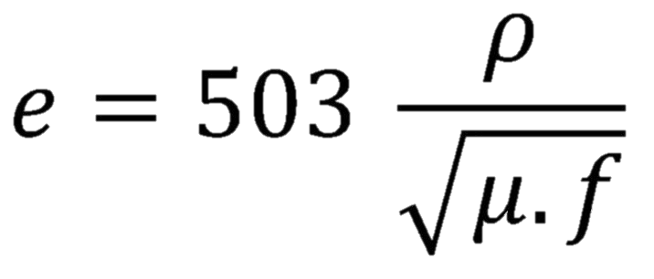
e = Thickness to be calculated //
p = Resistivity of the conductor
u = Permeability of the conductive material // f = Current frequency
For a copper conductor, the formula takes the following form:
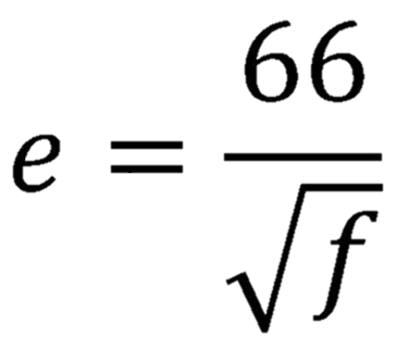
The value is given in millimeters.
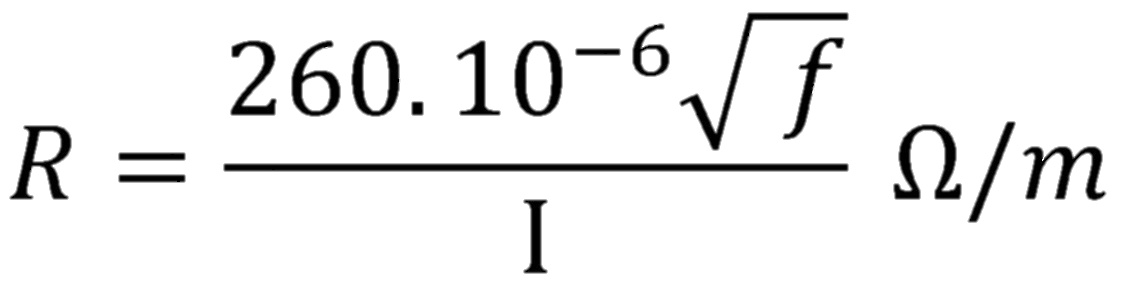
The resistance of an alternating current conductor is given by:
![]()
I = Perimeter in mm of the conductor section.
For copper, the formula becomes:
Eddy currents
When a ferromagnetic material is introduced into an alternating magnetic field, in addition to magnetization, an induced voltage is created; this produces an induced current which depends on the resistivity of the material. The current induced in the material is consumed in the form of heat (Joule effect) which is given by the formula:
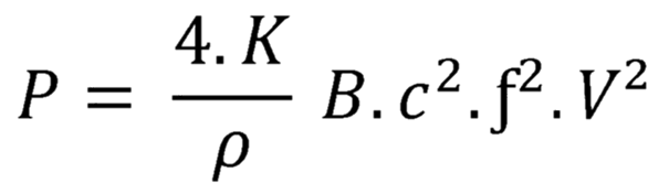
P = Power dissipated by eddy currents // K = Constant
p = Resistivity of copper // B = Maximum induction passing through the material
c = Thickness of the ferromagnetic material // f = Frequency // V = Volume of the ferromagnetic material
Capacity losses
Two conductors with different potentials accumulate electrical energy at the same time. The wires used in the manufacture of coils have this particularity, which allows us to speak of a sum of capacities distributed between the various turns of this one. The coils studied are subjected to an alternating voltage of high frequency, close to the resonant frequency which gives us a very high impedance as if they were in parallel with the ohmic resistance and the self-inductive coefficient of the coil. These concepts give us the conclusion that the capacity of the coil alone is equal to 0.55 times its diameter in cm. We can change the capacity of the coil by:
- Studying its dimensions
- Chercher le meilleur enroulement
- Distributing the currents in the coil and Insulating the conductors
The capacitance between two conducting wires is:
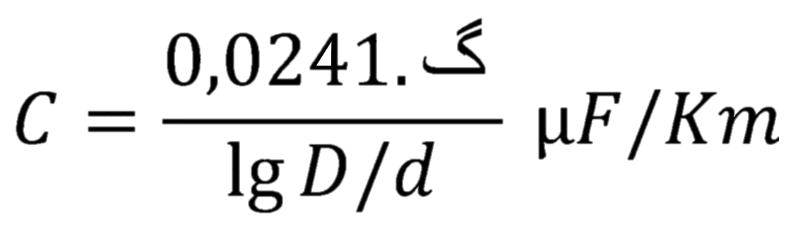
گ = Dielectric constant of the insulation // D = Diameter of the wire with the insulation // d = Diameter of the bare wire
Once the insulator has been chosen – which must have a very weak and must meet our objectives – we must analyze the D/d relationship. The lower it is, the better the capacity will be. The engineer must decide on the best solution taking into account the maximum current to pass through each wire and the voltage supported by the wires.
Adequate stranding of the wires forming the Litz cable will give the necessary uniformity to the capacitive distribution through this cable, in such a way as to increase the coil quality factor. By placing a spiral of natural silk, polyester or any other fiber that meets our specifications, as a support for the stranding of enameled wires, we do not increase the D factor. In addition, the spiral pitch of the fiber must be perfectly sized to that the Litz cables are not too rigid, in order to allow good winding without increasing the apparent inductance created between the spirals. The IgD/d relationship is a multiplying factor for inductance and must be as small as possible, and is a dividing factor for capacitance for which it must be as large as possible.
It is up to the engineer who calculates the coil to determine the parameters to be considered in the study of the circuit:
- Ohmic resistance
- Total induction
- Total capacity
The end result should be a coil ready for use in the circuit, with the best performance, lowest volume, and best quality while having the lowest resistance loss.
Litz cables are used to:
- Reduce losses by Joule effect
- Reduce losses due to eddy currents
- Use smaller magnetic cores
- Obtain capacity in small coils
- Get better quality
- Easy handling of cables for winding, due to wires fixed together
- Extra-flexible cables allowing core winding with a very small bend radius
Manufacturing standards
TESORAX ensures the manufacture according to the DIN 46.447 standard, and studies the cables according to the criteria:
- Number of wires depending on the cable diameter
- The type of insulation
- The support system
- Enamelled copper must be tinned. The outside diameter and other properties of the enamelled copper wire are selected by the manufacturer if the customer does not formally specify them. The outside diameter without insulation is the basis for calculating the outside diameter of the insulated cable: this is not used during reception checks.
High frequency cables (Litz cables) are defined by:
- Thickness of each elementary wire
- Total number of wires and bundling
- No stranding
- Insulating
The DIN 46.447 standard defines the types of cables according to each of these 4 criteria. Any question about the effective cross section of the conductor is defined as follows:
- Preset effective section: 0.70mm²
- Individual wire diameter: 0.10mm, i.e. a section of 0.007854 mm²
- Corresponding number of threads: 0.70 / 0.007854 = 89.13 theoretical threads. 90 threads will be used. The studied cable will have the following composition: 90x 0.10mm
Do not hesitate to contact us for any information: Our design office will be able to guide you in the cable solution that suits you best.